PROJ·002 · IOT INTEGRATION · STOCKHOLM
Sweden's ancillary services markets, FCR, mFFR, and aFRR, require battery fleets to respond to grid frequency deviations across activation windows ranging from a few seconds to several minutes. To participate, every asset in the fleet must successfully pass the Svenska kraftnät (SvK) prequalification process. In early 2023, Flower was building a distributed energy infrastructure around small-scale batteries and needed the engineering backbone to bring them into grid services at scale.
I joined as Automation & Integration Engineer. Over the following three years I worked across the full technical stack, from Modbus register level hardware commands integration to AWS cloud IoT architecture to real-time dispatch algorithms, scaling the fleet from zero to 1,300+ revenue-generating assets in production.
Each OEM family required independent investigation before any software could be written. The process started with IP scanning and device discovery on local networks, then opening a Modbus TCP connection (port 502, with OEM-specific exceptions) using pymodbus (ModbusTcpClient). Home network environments introduced the full set of practical reliability problems: DHCP-reassigned IP addresses requiring periodic rediscovery, socket-level timeouts requiring configurable retry and reconnection logic, and dropped TCP sessions that needed transparent re-establishment without interrupting active dispatch. Initial bring-up used manufacturer RS-485 serial dongles to validate low-level communication with each model line before switching to Modbus TCP in-field.
Register maps were incomplete or firmware-variant-dependent across all three families. Mapping them required systematic byte-level work: issuing FC03 (Read Holding Registers) requests, cross-referencing raw 16-bit responses against hardware behaviour, resolving data type encoding (16-bit unsigned, 32-bit signed split across two consecutive registers in big-endian word order), and identifying the correct Modbus unit IDs per device type. Setpoint injection and mode switching used FC06 (Write Single Register) and FC16 (Write Multiple Registers), with per-OEM timing constraints between sequential write commands to avoid firmware rejection. Three independent integration cycles: Huawei SUN2000 (SUN2000-3–10KTL-M1, SUN2000-12/15/17/20/25K-MB0), Sungrow SH-series (SH5–10RT, SH15/20/25T), and SAJ H2/HS2-series (H2-5K–30K-T2, HS2-5K–10K-T2), each with different register addressing schemes, data type encodings, mode arbitration logic, and power management behaviour.
The integration also had to account for variable household consumption profiles at each site, comparable to a HEMS context, where local load behaviour affects how much headroom the battery can offer to the market at any given moment. All hardware differences were abstracted behind a single command interface so the dispatch layer above remained brand-agnostic.
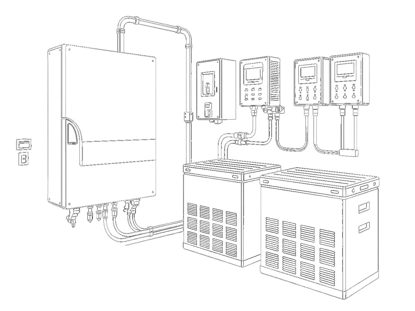
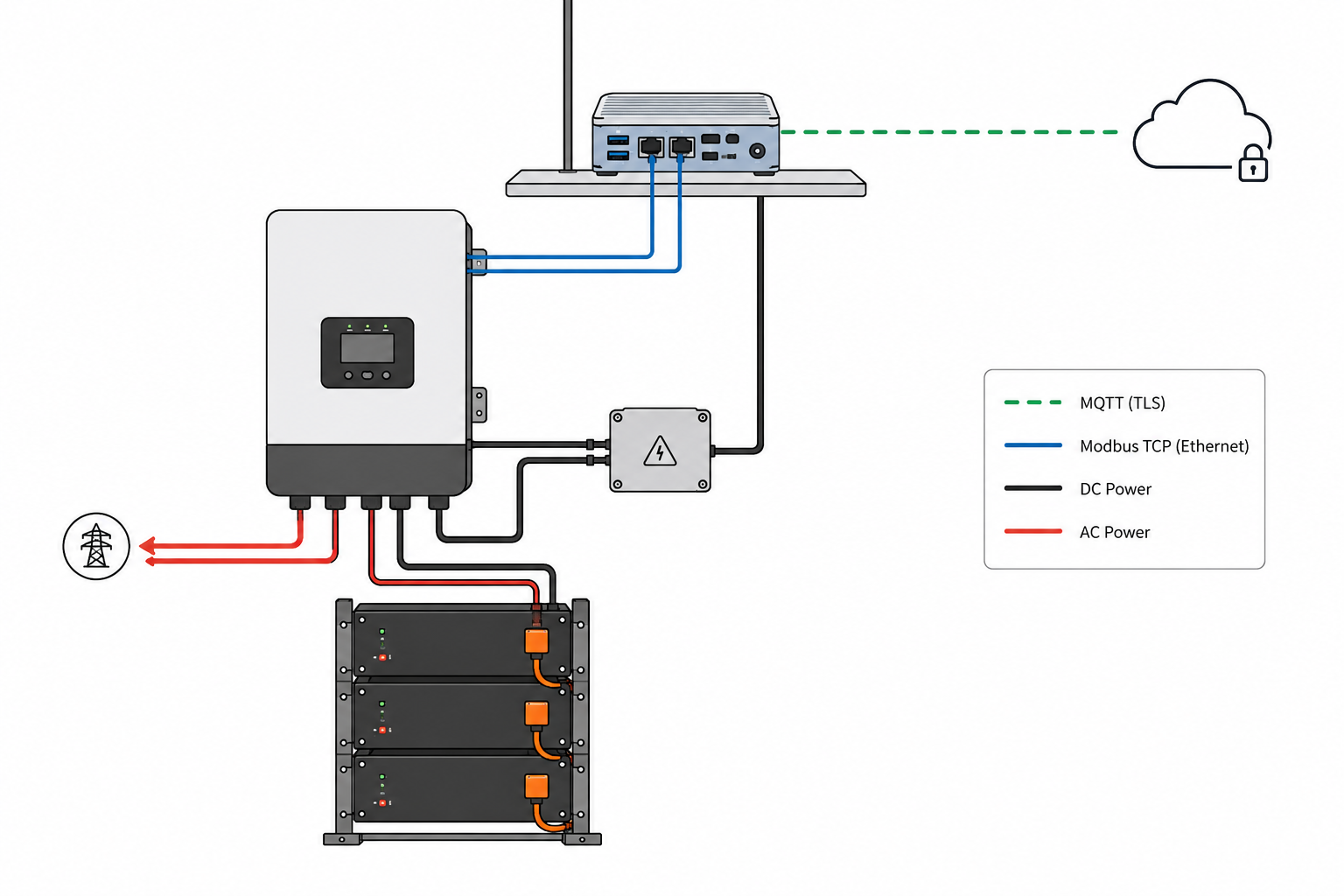
The edge software ran as a Python stack deployed via Greengrass onto Ubuntu-based FlowerHub controllers at each site. Each unit received dispatch setpoints over MQTT, commanded its inverters and batteries over Modbus TCP using pymodbus, and published telemetry back over MQTT, retaining local execution capability under connectivity loss and receiving OTA updates.
Setpoint handling required careful filtering: staleness checks to drop outdated inbound signals, a combined time-and-power-delta gate to suppress redundant Modbus writes without blocking legitimate ramp steps, and stop-command bypass logic so de-energise commands are never silently discarded. BMS fault register polling was added across all three OEM families, with bitmask decoding to structured fault codes published as telemetry.
The full CI/CD pipeline for the Greengrass component was built from scratch: syntax checks, linting, static type checking, dependency security audit, and unit test coverage on every pull request; automated build and publish to the private component registry on merge.
Passing SvK FCR prequalification required crossing multiple disciplines simultaneously. Each OEM family has different internal control logic, different activation thresholds, and different power response time constants, behaviours that must be understood at the hardware level before they can be shaped at the fleet level. Every dispatch command passes through several transitional layers: from cloud signal to device software, through the Greengrass runtime, over Modbus TCP to the inverter, and finally into the BMS and battery. Each layer adds latency and dynamic behaviour that affects the aggregate frequency response seen by SvK.
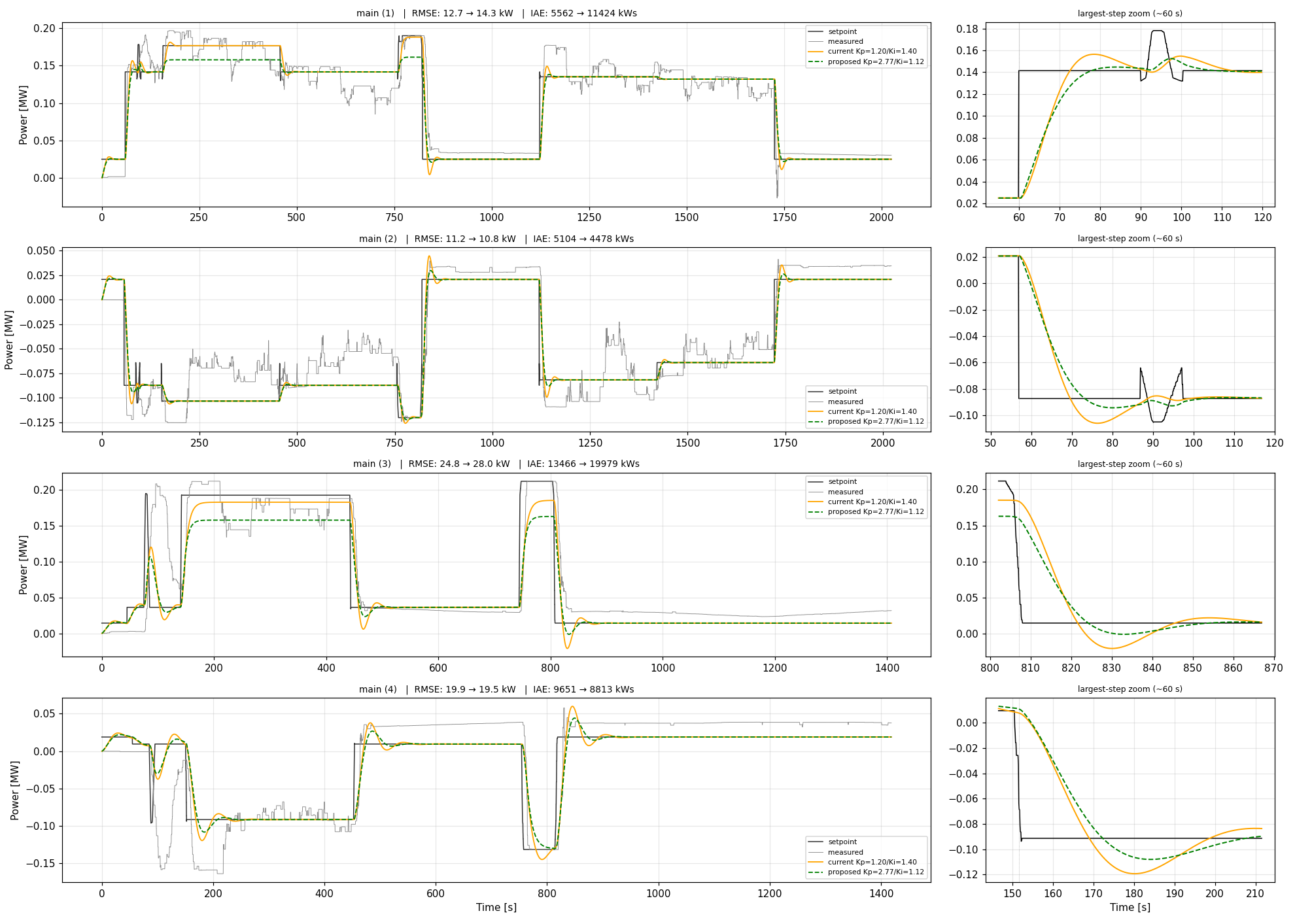
Getting a stable, compliant response across the full chain required combining hardware knowledge with control theory: frequency response analysis, Bode and Nyquist stability criteria applied to the end-to-end dispatch path, to ensure the power output ramp stays within SvK's activation envelope. The goal was fleet-level compliance, orchestrating 1,000+ individual sites, each averaging 10–20 kW, to act as a single virtual battery delivering MW-scale activations. SvK prequalifies the aggregate response; a single site with incorrect polarity, wrong timing, or a stale control state degrades the standing of the whole fleet.
A hardware abstraction layer over per-OEM drivers rather than direct per-brand code paths. The alternative was simpler to start: write integration code directly for each brand, ship it, and refactor later. The abstraction approach had a higher upfront cost, requiring a unified command contract before any brand was fully integrated, but it paid off at the third integration: onboarding a new brand became a register-map configuration file rather than a code change touching the control layer. It also proved its value during OEM firmware updates, which frequently change register maps and device behaviour, requiring only a configuration update rather than a software change.
The risk was getting the abstraction wrong early and paying the cost of rework at scale. It required investing time in hardware investigation upfront, before the contract boundaries were fully clear, to validate that the interface could actually represent all three families without leaking OEM-specific behaviour into the layers above.
Sending control commands to OEM inverters without interfering with their own built-in protection and management logic is harder than it looks. Inverters are not passive actuators: each OEM has its own internal state machine, safety thresholds, mode arbitration, and protection layers running independently of any external command. A setpoint that is valid from the fleet's perspective can be silently overridden, clamped, or rejected by the inverter's own firmware, and the only signal is a telemetry reading that doesn't match what was commanded.
Getting reliable, predictable behaviour required understanding not just the register map but the full operating logic of each model: when the OEM's internal mode takes precedence, which registers are advisory vs binding, and how protection limits interact with external setpoints under different SOC and temperature conditions. The answer varied across firmware versions within the same model family, requiring per-variant validation rather than a single integration test.
The part I would invest more in from the start is the initial connectivity layer: reliably establishing and maintaining the connection between the inverter, the local control device, and the network is the most common failure point in a home installation context. It sits below the software layer entirely, yet it determines whether everything above it can function. I would put more effort into building robust, opinionated guides and tooling for this phase, keeping the solution simple while making connectivity failures immediately visible and recoverable, especially given the variability of home network environments where the integration is deployed.